| This is just a quick entry to outline the latest development with the AI-Duino project. Having installed the ultrasonic sensor, I wrote a very messy sketch to make it obstacle avoiding. As I did not have a spare stepper motor and driver I chose to mount the ultrasonic sensor in a fixed position. Due to this, I made the AI-Duino turn completely to assess the space to its left and right (once it had encountered an obstacle). I have included the sketch for anyone who would like to use it. All comments, feedback and suggestions are welcomed. | obstacle avoiding robot sketchN.B. This sketch utilises the ultrasonic sensor library discussed here. Also, please ignore my messy and unhelpful comments within the sketch. #include <Ultrasonic.h> /*-----( Import needed libraries )-----*/ #include "Ultrasonic.h" /*-----( Declare Constants and Pin Numbers )-----*/ #define TRIG_PIN 12 #define ECHO_PIN 13 /*-----( Declare objects )-----*/ Ultrasonic OurModule(TRIG_PIN, ECHO_PIN); /*-----( Declare Variables )-----*/ void setup() /****** SETUP: RUNS ONCE ******/ { Serial.begin(9600); Serial.println("UltraSonic Distance Measurement"); Serial.println("YourDuino.com [email protected]"); // initialize the digital pin as an output. // Pin 13 has an LED connected on most Arduino boards: pinMode(5, OUTPUT); pinMode(6, OUTPUT); pinMode(10, OUTPUT); pinMode(11, OUTPUT); } void loop() /****** LOOP: RUNS CONSTANTLY ******/ { Serial.print(OurModule.Ranging(CM)); Serial.print("cm "); delay(100); //Let echos from room dissipate Serial.print(OurModule.Ranging(INC)); Serial.println("inches"); int right = 0; int left = 0; delay(500); if((OurModule.Ranging(CM)) > 30) //if clear { Serial.print ("More than 30 CM"); Serial.print (" - Clear to Drive Forward"); digitalWrite(10, HIGH); // set the LED on ... forward digitalWrite(6, HIGH); // set the LED on ... forward //delay(1000); // wait for a second //digitalWrite(10, LOW); // set the LED off //digitalWrite(6, LOW); // set the LED off //delay(10); // wait for a second Serial.println (" - Drove Forward 1000"); delay(100); } if((OurModule.Ranging(CM)) < 30) //if obstical is in the way { Serial.print ("Less than 30 CM"); Serial.print (" - Obstical Detected"); Serial.print (" - Searching Surroundings"); digitalWrite(10, LOW); // set the motors off digitalWrite(6, LOW); // set the motors off digitalWrite(6, HIGH); // set the LED on ... turn left digitalWrite(11, HIGH); // set the LED on ... turn left delay(600); // wait for 6/10 second digitalWrite(6, LOW); // set the LED off digitalWrite(11, LOW); // set the LED off delay(100); // wait for a second Serial.print (" - Turned Left 90 Degrees "); left = (OurModule.Ranging(CM)); //take distance reading - left Serial.print(left); //digitalWrite(6, LOW); //digitalWrite(11, LOW); digitalWrite(5, HIGH); //turn right 180 degrees digitalWrite(10, HIGH); delay(1200); digitalWrite(5, LOW); // stop digitalWrite(10, LOW); Serial.print (" - Turned Right 180 Degrees "); right = (OurModule.Ranging(CM)); //take distance reading - right Serial.println(right); digitalWrite(6, HIGH); // return to centre digitalWrite(11, HIGH); delay(600); // wait for 6/10 second digitalWrite(6, LOW); //stop digitalWrite(11, LOW); delay(10); int dif = (left + 1000) - right; //working out if left or right has more space - less than 1000 means right has more room Serial.println (dif); if(dif>1000) // more room on the left { digitalWrite(6, HIGH); //turn left digitalWrite(11, HIGH); delay(600); //180 degrees digitalWrite(6, LOW); //stop digitalWrite(11, LOW); Serial.println(" turning 90 left - more space left"); } if(dif<1000) // more room on the right { digitalWrite(5, HIGH); //turn right digitalWrite(10, HIGH); delay(600); //180 degrees digitalWrite(5, LOW); //stop digitalWrite(10, LOW); Serial.println(" turning 90 left - more space right"); } } //} //void loop() { } |
|
0 Comments
Ok, so now I have the motor driver working, it is time to install it into the Bigtrak. The first job was to remove the circuit board, key pad and disconnect the wiring. With that done, I connected the motor driver to the Bigtrak's motors, 4.5v power supply and Arduino Uno. The next job was to connect the Arduino to a separate 9v power supply, then screw the boards in place. Luckily, there are a few screw holes no longer used by the original board. Once everything was in place I installed a variation of the blink sketch to test for functionality (code included at the bottom of this entry). To see the Bigtrak in action check out these YouTube videos:
All comments, suggestions and feedback are welcomed.
Test Code void loop() { digitalWrite(11, HIGH); // Back digitalWrite(5, HIGH); // Back delay(1000); // digitalWrite(11, LOW); // digitalWrite(5, LOW); // delay(1000); // wait for a second digitalWrite(10, HIGH); // forward digitalWrite(6, HIGH); // forward delay(1000); // digitalWrite(10, LOW); // digitalWrite(6, LOW); // delay(1000); // wait for a second digitalWrite(6, HIGH); // turn left digitalWrite(11, HIGH); // turn left delay(1000); // digitalWrite(6, LOW); // digitalWrite(11, LOW); // delay(1000); // wait for a second digitalWrite(5, HIGH); // turn right digitalWrite(10, HIGH); // turn right delay(1000); // digitalWrite(5, LOW); // digitalWrite(10, LOW); // delay(1000); // wait for a second } 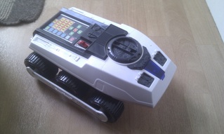 In order to experiment with artificial intelligence, I need a platform to play with, therefore, I have hacked a Bigtrak. This entry is a description of my journey so far. The Bigtrak is a children's toy which can be programmed, via a keypad, to drive around and shoot things with its 'photon laser'. Inside, there is a main circuit board, 3xD cell compartment (4.5v), LED (Photon Laser), speaker and twin gear box (motors circa 3v, no-load = 150mA, loaded = 500mA ) (image right). The Plan
Test its roaming ability with basic program. Install sensors. Options including, but not limited to: ultra sonic, light, reflective surface, impact, tilt and sound. Install actuators. Options include, but are not limited to: stepper motor (360 degree rotation of ultra sonic sensor) and LED. Design program to allow the Bigtrak to behave in response to environmental stimulus. After working with the Nanode RFX for some time, I decided that the Arduino Uno would be more appropriate for this project. Therefore, after purchasing the Uno, I looked for an appropriate motor controller. I needed something that could handle a peak of 500mA and found, curtsy of the Raspberry PI forum, the "Dual H Bridge DC Stepper Motor Drive Controller Board Module Arduino L298N #236" (long name but should be searchable). After around 20 minutes I had a working circuit (see video).
Emotobot is one of the latest projects to be undertaken at ICM prototype by myself Steven Gartland and anyone else who fancies an input.
The project started through my old love of Psychology and my new love of building things. I have long been aware of models of human behaviour and motivations that have helped develop some impressive therapies (for when things go a bit wrong). These models have been fine tuned and built on over the past 50 years or so, making it very hard to gain an understanding of how they all interact to create the human condition. Subsequently, it is the aim of this project to develop a system for a robot, based on the many psychological models, that exhibits behaviours motivated by their interplay. Once the system is up and running, we can observe changes within the system as an addition to the stimulus-response approach of Behavioural Psychologists. The first steps: * Choose a platform * Learn how to program * Replicate Anxiety Simple! Choose a platform After much research and questioning of peers (thanks Matt) I decided to go for the Nanode RFX for the platform. It is a prototyping board much like the Arduino but with a few more bells and whistles on it, i.e. an RF unit, Ethernet controller, real time clock and an S.D. card slot. This will, I hope, make it more than capable for what I need in the short term and the ability to expand as it grows with all the extras. Learn How to Program Apart from a little dabbling with BBC Basic as a child (on the Spectrum 48k), I have never had any experience with programming and I must admit it was a little daunting. Luckily, I had many experts on hand to advise. I began coding, using the Arduino IDE and, after a few set up issues, it was nothing like as hard as I thought it would be (thank you cut and paste). Replicate Anxiety (The hard bit) Anxiety in humans is viewed by many Psychologists as a dynamic affair. Levels of anxiety change from moment to moment and are influenced by perceived changes in our environment and our thought processes. Our 'resting' anxiety levels (levels of anxiety that is our personal norm), develops over our lifetime caused by our experiences, both internal and external. Anxiety effects many aspects of the human psyche as well as physical processes. For example if you were to encounter a lion in your front room you would feel worried - shaking, sweating and butterflies in the tummy. All of which are physical functions of anxiety caused by Adrenalin being released into the blood system to prepare for 'fight or flight'. As anxiety is one of the oldest (evolutionary speaking) of human processes, it is helpful to regard it as a core process. Therefore, it make sense to begin with this process and then build other (newer) processes on top. A detailed account of my programming a simulation of anxiety will be included in my next post. |
Steven GartlandCreator and Developer of Ai-Duino Categories |
 RSS Feed
